


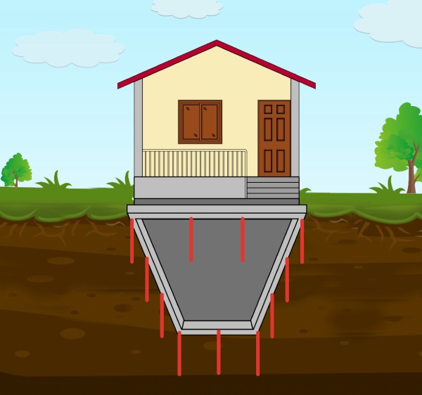
Micropiles are considered a deep foundation system along with drilled piers or driven piles. Geo technical engineers often recommend a deep foundation system over shallow foundation system for important and large buildings. Most notably when the soil conditions are poor or their loads are exceptionally high. Micropile installation is usually a quick process as it uses adaptable mobile drilling equipment to install the piles. They are often an economical alternative to other deep foundation systems. Usually, due to difficult ground conditions or when site access is restricted, micropiles can be designed to handle lateral loads or bending moments along with axial loads. Design assumptions are often obtained from geotechnical reports and bond values are verified in the field by the use of tension, compression or lateral load tests.
History
According to ‘U.S. Department of Transportation’, micropiles were first established in the early 1950s in Italy. They were invented in response to serious demand for innovative techniques for underlying historic buildings which sustained damage during World War II. A credible method was needed to support the structural loads with minimal movement. An Italian contractor called Fondedile, developed Palo radice or “Root Pile” which is a small-diameter, cast-in-place and lightly reinforced grouted pile. Fondedile then implemented the use of micropiles in North America in 1973.
Initially, the micropiles technology did not become popular in the United States. But eventually by the 80’s, it started gaining expanded applications. The micropiles have been excessively used mainly as an element for foundation support to resist static as well as seismic loading.
According to ‘Deep Foundation Institute,’ Micropiles are not new, but are not well known. They have been used for a very long period as foundation elements as driven piles since more than a thousand years – and several European cities are built on thousands of piles.
What is a Micropile?
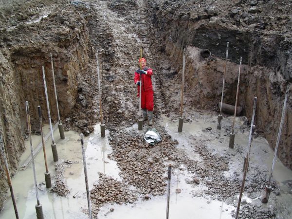
A micropile is a high-strength, small diameter, non-displacement pile whose dimension is typically less than 300 mm i.e. 12 inches. The standard length of a micropile typically ranges from 5 to 30 metre. It consists of a steel casing that is usually between 4 to 12 inches (100 mm to 300 mm) in diameter. Even these small elements are able to develop a capacity that ranges between 10 and 300 tons. It is generally constructed by drilling a borehole first and then placing steel reinforcement, followed by grouting of drilled hole. Micropiles having the compressive strength of 1,000 kN or larger are used in the field.
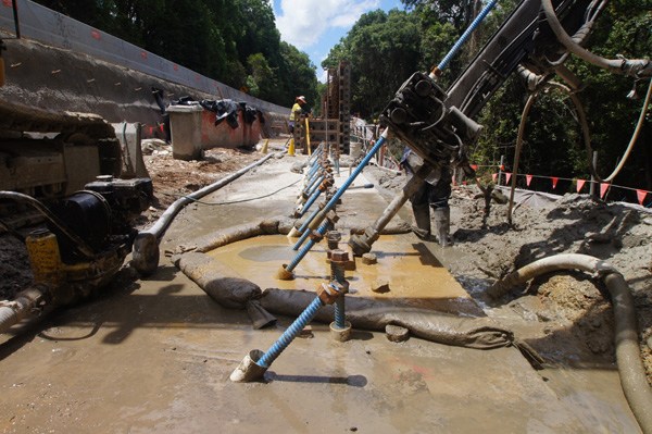
The high capacity micropile installation method involves drilling and pressured grout injection technique. Additionally, it uses steel pipes as reinforcements along with the deformed reinforcements in order to construct high capacity micropiles having maximum bearing capacity. The installation of the micropiles are done by methods that causes the least disruption to adjacent structures, soil, and the environment. They can be installed in soil of any type and places where the ground condition is good.
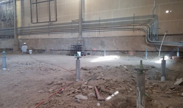
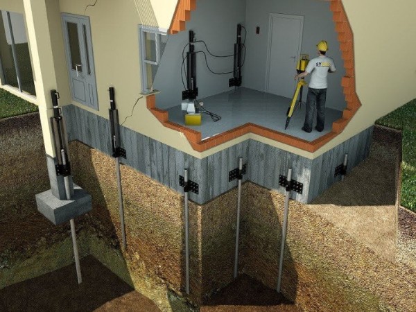
Since the installation of micropile causes less vibration and noise, they are often used in underpinning the existing structures. For underpinning existing structures, specialized drilling equipment is often required in order to install the micropiles from within the basement or other facilities having limited headroom. The structural capacity of a micropile can be increased by increasing the cross-sectional and surface areas. However, the structural capacities of a micropile as compared to other conventional foundations, rely on high-capacity steel elements. These steel elements generally occupy as much as one-half of cross section of a drill hole. The special method used for drilling and grouting during the micropile installation, allows high grout-ground bond along the interface. The transfer of load from grout to the ground in a micropile is through friction.
How is Micropile Different from Other Conventional Piles?
Micropile may be considered as a great substitute for conventional driven piles or drilled shafts or even as one of the components in a composite soil/pile mass, since it can withstand relatively significant axial and lateral loads. The main difference between micropiles and the other deep foundation systems are that, the micropiles can achieve the capacity of the grouted bond zone as opposed to being an end bearing system because the capacity is determined in the bond zone. No verification of bearing strata below is required. The special characteristics of the micropile that make it different from a conventional pile are mentioned below:
Design Characteristics
- In spite of having lesser diameter, it provides large bearing capacity to the structure.
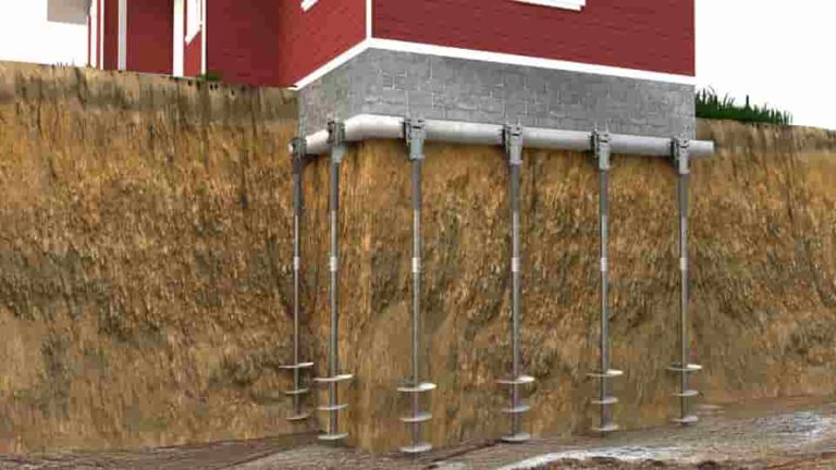
- The bearing capacity of micropiles provide both axial and pull out resistances. Hence, this pull-out resistance can be used effectively when micropiles are used for reinforcement of retaining walls, seismic retrofit or even slope stabilization.
- It can be used individually as bearing piles or they can be used in a group for soil strengthening.
Construction Characteristics
- They are drilled into the ground with boring machines that produce very little sound or vibration caused during construction process.
- Since the diameter of a micropile is 300 mm or less, it results in minimal influence on the buried obstructions and existing structures. Additionally, only lesser volume of earth needs to be excavated for the installation of a micropile.
Classification of Micropiles / Types of Micropiles
Based on Design Application
Case 1: In this type, the micropile elements are loaded directly and the reinforcements resists the majority of the applied load, as they transfer structural loads to a deeper and more competent stratum, they can be used as an alternative to conventional type of piles.
Case 2: This type of micropile is also referred to as “Reticulated Micropile”. In this type, the micropile elements are internally reinforced in the soil, to make the soil composite that resists the applied loads.
Based on Construction Type
Type A: Gravity Grout:
In this type, the grout is placed under the gravity head only. It can be achieved by using only the sand-cement mortar or neat cement. The micropile excavation may be under-reamed in order to increase the tensile capacity. This technique is not very common or used with any other micropile foundation type.
Type B: Pressure through Casing:
This type of micropile indicates that cement grout is placed in the hole under pressure as the temporary drill casing is removed. The pressures range from 0.5 to 1 MPa (72 to 145 psi i.e. 5 kg/cm2 to 10 kg/cm2) in order to avoid hydro fracturing, surrounding ground or causing excessive grout takes.
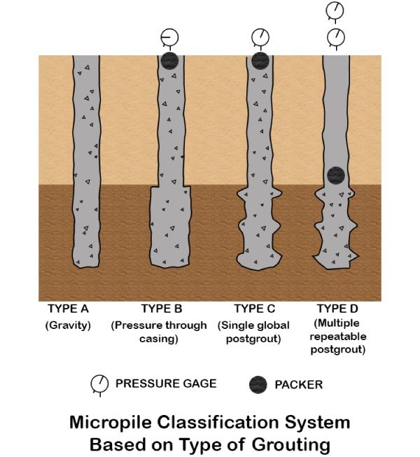
Type C: Single Global Post Grout:
Type C can be done in a two-step process of grouting which includes:
- Same as that as Type A; (2)
- After approximately 15 to 25 minutes, prior to hardening of the primary grout, similar grout is injected once through a sleeved grout pipe without the use of a packer at a pressure of approximately 1 MPa (145 psi i.e. 10 kg/cm2).
Type D: Multiple Repeatable Post Grout:
Type D is also done in a two-step process of grouting similar to that of Type C. With this method, neat cement grout is placed under gravity head just as in case as with Types A and C and may be pressurized as for Type B. After hardening, additional grout is injected through a sleeved grout pipe at a pressure of approximately 2 to 8 MPa (290 to 1,160 psi i.e. 20 kg/cm2 to 80 kg/cm2). This pile type is commonly used worldwide, and is referred to as the IRS (Injection Repetitive Selective) in France.
Design of Micropiles for Structure Foundations
The basic principle of micropile design varies a little from that of a drilled shaft. The design system must be competent of handling the anticipated load conditions with resulting displacements being within the allowable limits. Micropiles have a comparatively small cross-sectional area; hence the design is usually controlled by the structural considerations. A step-by-step generalized method for the design of micropiles used for structural foundations is described here in.
Step 1: Evaluate Project Requirements and Micropile Feasibility:
It is essential to consider various foundation types and to select the right alternative based on the requirements of superstructure, subsurface conditions, and the foundation cost. Foundation types may include shallow foundations which consist of spread footing or mat/raft foundations or deep foundations which consist of driven piles, drilled shafts, or micropiles. While assessing the micropile feasibility for a particular project, micropiles will most often be compared to drilled shafts or driven piles.
Step 2: Review available information and Geotechnical Data:
The subsurface exploration, laboratory testing, and evaluation of geo technical design parameters for the design of micropiles used for structural foundation support is similar to that for either driven piles or drilled shafts. In general, all geotechnical data interpretations should be provided. The basic character and extent of the soil strata determined from the geotechnical investigation can be verified during pile installation by monitoring and logging of the penetration rates, drilling action, flush return, and soil cuttings.
Step 3: Develop Applicable Loading Combinations:
The anticipated loads for consideration in design (e.g., maximum compression load, tensile load, and longitudinal overturning moments) will usually be provided by the structural engineer as part of the design criteria package.
Step 4: Preliminary Design of Micropiles:
- Selection of Micropile Spacing: In all cases, the centre-to-centre spacing between individual micropiles should be at least 760 mm (30 in.) or 3 times the diameter of micropile, whichever is greater. The spacing of micropiles for structural foundation support will also depend on the specific application. Micropile spacing and layout will be determined by the foundation/ structural engineer.
- Selection of Micropile Length: The maximum length of a micropile that can be achieved using common track-drilling equipment is greater than 90 m (300 ft.). Typically, however, micropiles of such lengths would be very expensive and a practical limit for most projects may be in the order of 30 m (100 ft.).
- Selection of Micropile Cross Section: In general, it is preferable to install few higher capacity micropiles as compared to a larger number of lower capacities micropiles to resist a given set of foundation loads.
- Selection of Micropile Type: The selection of the micropile type should be left to the discretion of the designer/contractor. The owner should provide specific performance criteria (e.g., movements of structures) as part of the bid package so that the Contractor can select an appropriate industry-accepted drilling and grouting procedure.
Step 5: Structural Design of Micropile Cased Length:
According to ‘AASHTO’ (American Association of State Highway and Transportation Officials), structural design of cased length of micropiles is done by evaluating the allowable compression load.
Evaluation of Allowable Compression & Tension Load for Cased Length
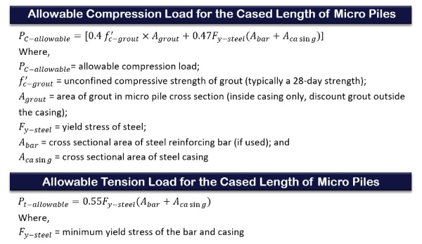
The allowable compression load for the cased length of a micropile is given as:
Step 6: Structural Design of Micropile Uncased Length:
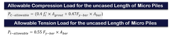
The allowable compression load for the uncased length of micropiles is given as:
Step 7: Revise Micropiles Design:
Based on the calculations performed in Steps 5 and 6, the micropile cross section should be modified if the allowable compressive or tensile load (for either the cased or uncased length) is not sufficient to carry the compression or tensile design loads provided as part of Step 3.
Step 8: Evaluate Geotechnical Capacity of Micropiles:
(a) Establish Stratum for Bond Zone:
As part of this design step, all borings should be reviewed to identify strata appropriate for the micropile bond zone and to identify significant variations in subsurface conditions.
(b) Select Ultimate Bond Stress and Calculate Bond Length:
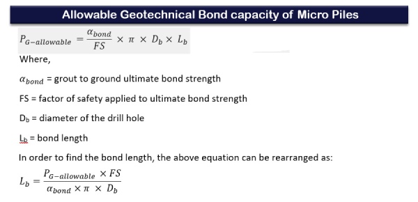
The allowable geotechnical bond capacity, PG-allowable, is calculated as:Where, for the above equation is equal to the maximum compression or tension load for design. For most micropile projects, the contract documents will provide a minimum bond length. This bond length will be based on the evaluation provided in the above equation.
(c) Evaluate Micropile Group Compression Capacity:
The efficiency of a micropile group installed in cohesive soils is a function of the centre-to-centre spacing of the micropiles and contact condition between the bottom of the micropile footing cap and the soil near the ground surface. The group capacity to be used for design is evaluated using the following steps:
- Calculate ultimate group capacity as:
Qg = (α bond ×π ×Db ×Lb) × number of micropiles in group × η
- Calculate ultimate group capacity according to the above equation and use lower value for design.
- Use a FS value of 2.0 to calculate an allowable group capacity.
(d) Evaluate Micropile Group Uplift Capacity:
The design of micropile groups subject to uplift forces follows the method described in FHWA NHI-05-042 (2005) for uplift capacity for driven piles in cohesion less soils and for driven piles in cohesive soils.
Step 9: Estimate Micropile Group Settlement:
In general, methods used for estimating settlements of driven pile groups are applicable for micropile groups. The major components of settlement that need to be assessed include: (1) settlements of the ground in which the micropiles are constructed; and (2) elastic compression/tension of an individual micropile. These settlements are added together to evaluate the total settlement of the micropile group subject to the design load and are then compared to the allowable settlement.
Step 10: Design Micropile Connection at Pile Cap:
Unless a single micropile is used to support a load, a pile cap (footing) is necessary to spread the structure loads and any overturning moments to all the micropiles in the group. After the pile is installed, the annulus between the core hole and the micropile is cleaned (usually via pressure washing) and filled with non-shrink cement grout.
Step 11: Develop Load Testing Program:
For load testing, maximum test loads should not exceed 80 percent of the ultimate structural capacity of the micropile. The resulting stiffer micropile can adequately confirm the grout-ground bond strength for production of micropiles, but it is likely not to provide representative structural displacement behaviour.
Step 12: Prepare Drawings and Specifications:
When the design has been finalized prepare drawings with the specifications and procedures that will be used. To verify micropile capacity load testing should be defined.
Advantages of Micropiles
- They have a capacity of over 1000 KN to 3000 KN. (100 to 300 tonnes)
- Micropiles are ideal for under-pinning foundations as well as load enhancement of the existing foundations.
- Due to their wide range of installation, they can be economically installed in hard ground conditions.
- They provide high degree of redundancy and also implies tight access installation
- They give out limited or no vibrations
- They can be drilled through obstructions in soil, like boulders, rubble etc.
Disadvantages of Micropiles
- They require special equipment and skilled labour.
- They have great limitations for their lateral capacity.
- They have high slenderness ratio which may not be appropriate for seismic loads.
Application of Micropiles
- Stabilizing difficult terrains
- Supporting heavy loads
- Maintaining restrictive budgets
- Foundation rehabilitation and repairs
- Foundation stabilization of adjacent structures
Conclusion
In conclusion, the micropiles are desirable foundation type in spite of having a relatively high cost in comparison to the other piling systems. The micropiles provide high carrying capacity with lesser constrains and a self-sustained operation. Therefore, this type of piling system is desirable for both the foundation designer and the client. Additionally, the high-capacity micropiles have been proven to have high ductility and resistance against earthquakes which only makes them more attractive and efficient.
Moreover, Micropiles can be used as both normal foundation piles and as compensation piles for certain remedial works, especially those in that areas having site constraints.
- In terms as design aspects, they can be designed either as rock socketed piles or as soil friction piles. The factor of safety should be at least two, for both structural and geotechnical designs.
- During the installation of the micropiles, the percussion drilling technique is mostly desirable. But in sensitive grounds and soil having less cohesion, mostly rotary drilling having temporary casing and a stabilizing fluid is preferred.
- Micropiles can be a costlier alternative to support lateral loads or a large bending moment.
Also Read:
Know the Causes of your Foundation Cracks
The Foundation in Black Cotton Soil/Expansive Soil Mystery Revealed
What Should be the Minimum Depth of Foundation for New Home?
Image Courtesy: Image 2, Image 3, Image 4, Image 9 – mikrovai, Image 10
Author Bio
Arfa Falak – My name is Arfa Falak and I have my graduation in BE (civil). I live in Bangalore. I am an aspiring design Engineer.